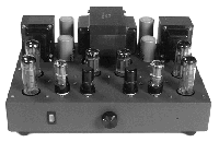
Here are the Randall Amplifier (Mk II) schematics in Adobe
Acrobat format:
 Randall Amp
page 1 (PDF: 66Kbytes)
 Randall Amp
page 2 (PDF: 118Kbytes)
The differences between the original Randall Amp and the Mark
II version are:
- Filter chokes changed from 1.5H/75 ohm to
4.0H/65 ohm. These larger chokes have to be mounted diagonally
under the chassis for them to fit. The residual hum level is
reduced and users report a more "dynamic" sound.
- Cathode compensation capacitors (C105, C205)
changed from .0039 uF to .012 uF. This gives flatter frequency
response at 20KHz.
- Shielded wire from RCA jacks to volume control
and from speaker terminals to feedback circuit changed to twisted
26 AWG wire-wrap wire.
- The rectifiers were changed from the trouble-prone
Chinese 5AR4 to the reliable Philips ECG 5V4GA (military surplus).
- The paralleling of the rectifier sections
was changed so that each side of the transformer secondary goes
to the two sections inside a rectifier, instead of being spread
across two rectifiers. This helps reduce arc-over when the rectifiers
have different characteristics.
You can also see the write-up and pictures of the Randall Amp
here.
The Randall Amp "Hall of Fame" - a collection of
outstanding variations of the Randall Amp is here.


![]() Randall Amp
page 1 (PDF: 66Kbytes)
Randall Amp
page 1 (PDF: 66Kbytes)![]() Randall Amp
page 2 (PDF: 118Kbytes)
Randall Amp
page 2 (PDF: 118Kbytes)